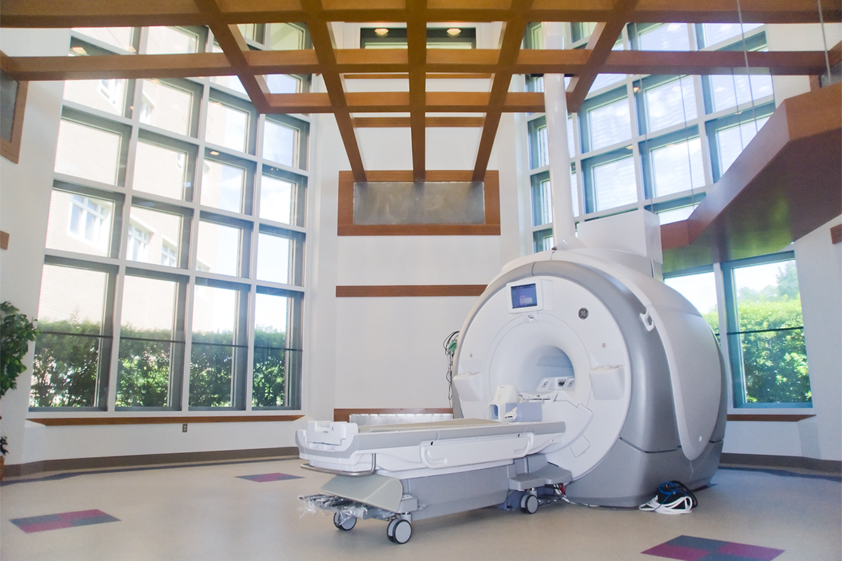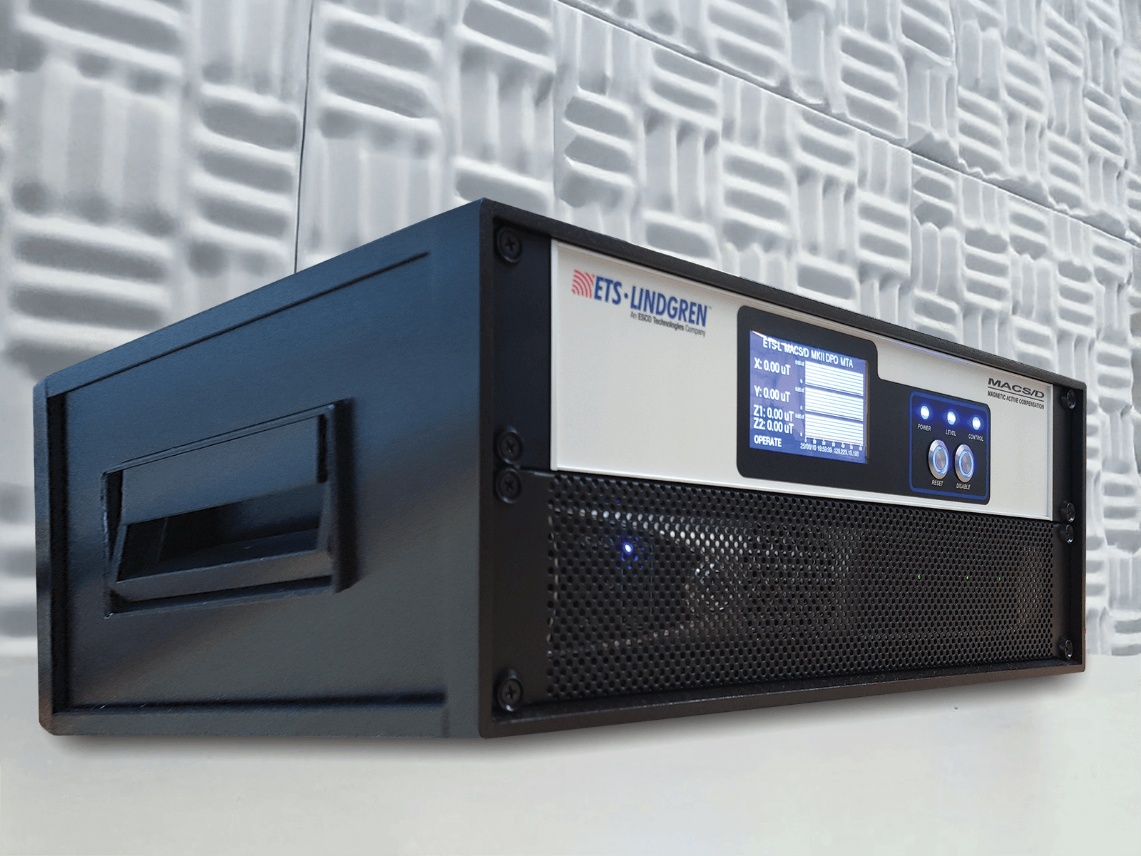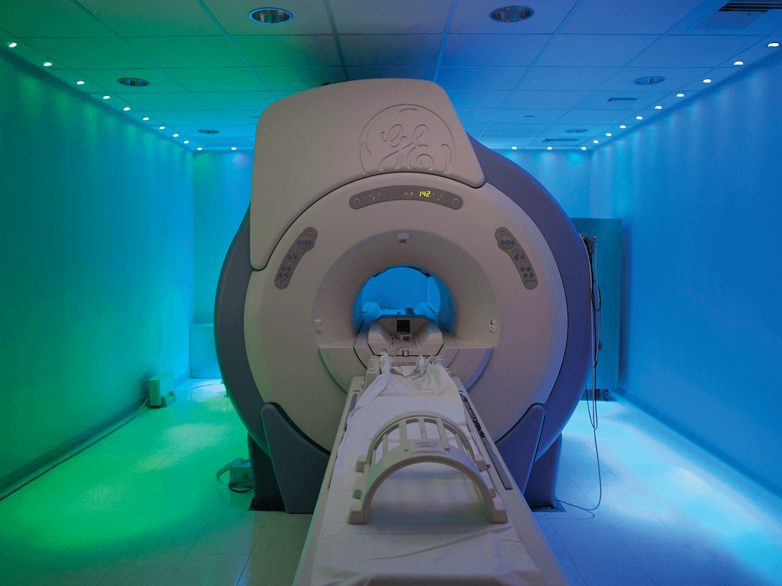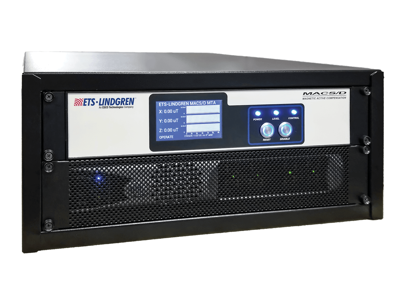

MACS/D (Magnetic Active Compensation System) for MRI
Magnetic active compensation system stabilizes MRI environments by canceling dynamic magnetic interference and maintaining consistent field conditions, even in demanding urban or industrial locations.
Add to FavoritesRemove from Favorites
Add to Favorites
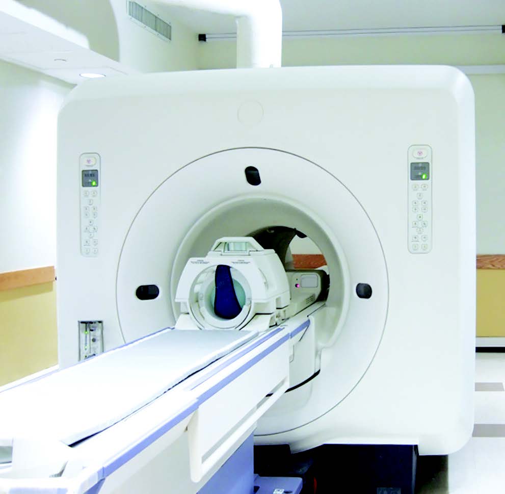
Magnetic Compensation System for Stable MRI Performance
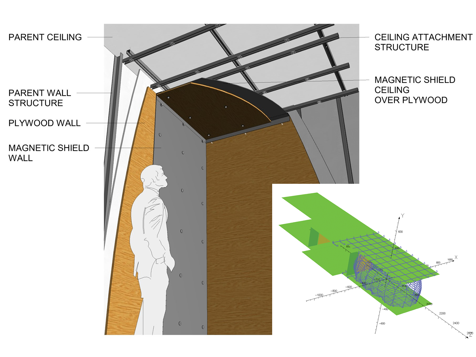
Magnetic active compensation system provides high-performance attenuation of fluctuating magnetic fields that can disrupt MRI imaging quality and system stability. Using digital signal processing, tri-axial coil drivers, and ACR technology, the system corrects both AC and DC environmental interference over a wide frequency range. It is designed for challenging locations affected by elevators, trains, vehicles, and nearby electrical or magnetic equipment.
Key Advantages:
- Three-axis compensation with high-power coil drivers for strong field correction
- Real-time digital processing with enhanced isocenter attenuation
- Remote monitoring and diagnostics through secure VPN access
- Automatic restart and self-testing after power interruptions
- This system maintains stable imaging conditions, extends site flexibility, and supports reliable MRI operation in environments with persistent magnetic disturbances.

Case Study : Category : Healthcare
ETS‑Lindgren’s engineering experts were put to the test, quite literally, to diagnose and fix a problem on a magnetic resonance imaging (MRI) project at a leading hospital in Kowloon, Hong Kong. This…
Case Study : Category : Healthcare
ETS‑Lindgren upgraded Mount Sinai Union Square's MRI with MACS/D to eliminate subway-induced interference, ensuring clear, artifact-free images for better patient care.