Tapered Antenna Chamber Offers Plane Polar Near and Far Field Testing

ISRO in Ahmedabad is involved in the development of advanced antenna technologies for communication, remote sensing and navigation as well as earth station programs. In order to meet the requirements of these technologies, a comprehensive test facility is crucial for the characterization of large size antennas at various frequencies. To meet these challenging requirements, ETS‑Lindgren designed and installed a combined Plane Polar Near Field (PPNF) and Far Field (FF) test facility which may be utilized for both characterizing gravity sensitive antennas and for characterization of low frequency antennas. Both test capabilities are housed in a single tapered anechoic chamber. Utilizing simulations and raytracing calculations, ETS‑Lindgren lent ISRO its considerable expertise in the design and installation of tapered anechoic chambers. Two test reports on similar chambers documented ETS‑Lindgren’s veteran capabilities.
Tapered Chamber Overview
- Nominal inside dimensions are 12 m (39 ft) wide x 12 m (39 ft) high x 36 m (118 ft) long. This includes a 12 m (39 ft) wide x 12 m (39 ft) high x 12 m (39 ft) long test region and a 24 m (78 ft) long tapered section.
- The center of the Quiet Zone to ground is 6 m (20 ft) high.
- Constructed of galvanized steel sheets that are attached with screws to a steel structure. The absorbers are attached directly to the galvanized sheets using special adhesive.
- The chamber is lined with pyramidal type RF anechoic absorbers, wedge and flat sheet type.
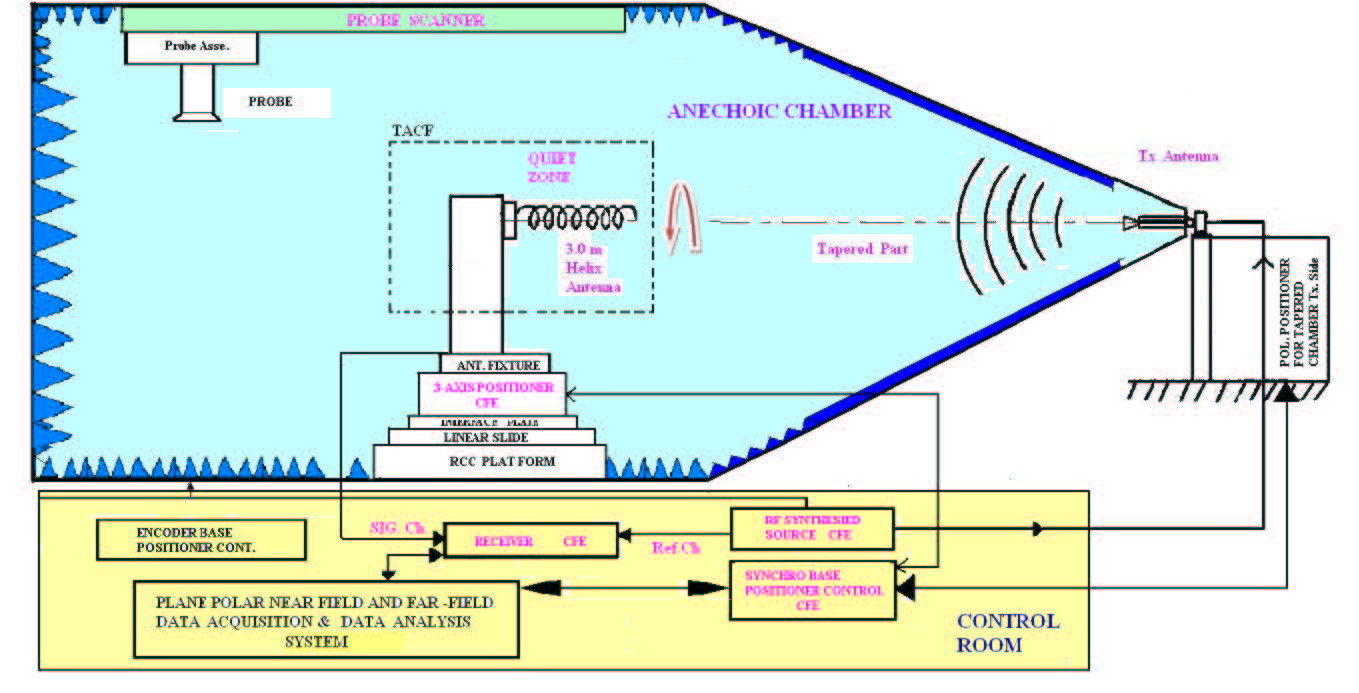
- The chamber is capable of three modes of operation:
– Plane Polar Near Field Measurement
– Tapered Chamber for Far-Field Measurement
– Passive Inter-Mod Product Testing
Chamber System Level Performance Specifications
- Validation of chamber performance was demonstrated by performing a free space VSWR reflectivity measurement per IEEE standard test procedures for antennas per ANSI/IEEE Standard 149 – 1979.
- Frequency operating range is 200 MHz to 20 GHz.
- Quiet Zone size is 3 m (10 ft) diameter; reflectivity performance is -30 dB or better at 200 MHz, -35 dB or better at 400 MHz, -40 dB or better at 600 MHz, -45 dB or better at 800 MHz, -48 dB or better at 1 GHz, and -50 dB or better at 2 GHz to 20 GHz.
- Accuracies: Gain: ± 0.3 dB, Side – Lobe: ± 1.0 dB at -30 dB signal level, Cross Polarization: ± 2.0 dB signal level.
- Absorber power handling capability of 1.5 Kw/m2 per specified duration.
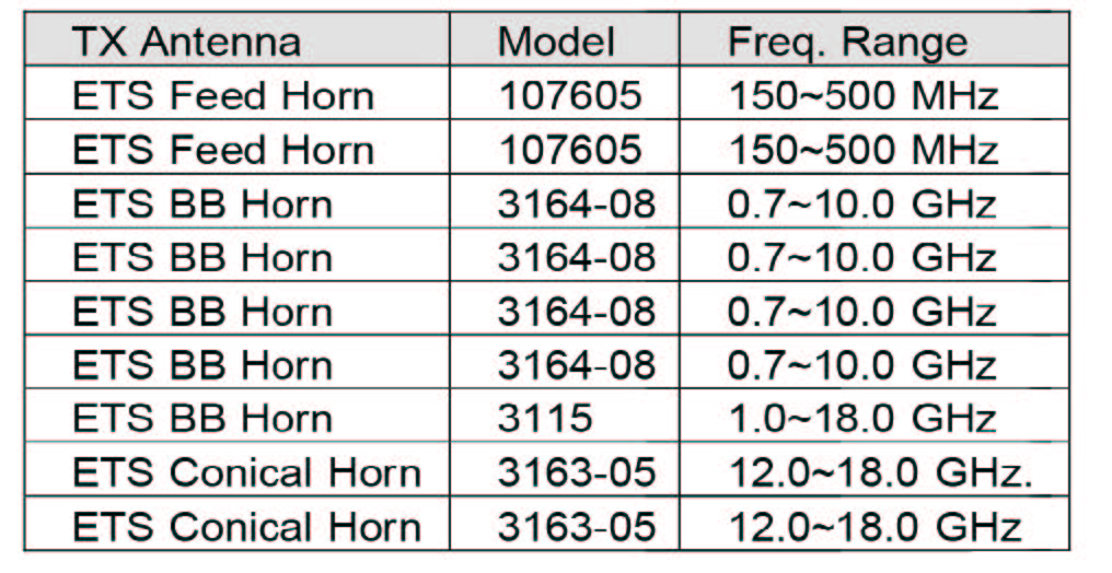
Transmit Source Antennas
The ETS‑Lindgren antennas provided met the following specifications:
- Frequency range of 200 MHz to 2 GHz; gain 6 to 9 dBi, and linear polarization.
- Side lobe level 20 dB ± 1 dB.
- Cross polarization in all E, H, D planes at on axis at less than -40 dB ± 2 dB.
- Return loss better than 15 dB.
Microwave Absorber
- High performance, combustion limiting polyurethane made from urethane foam and impregnated with a dielectrically matched conductive carbon.
- A Naval Research Lab (NRL) broadband swept frequency arch was used for testing at 750 MHz to 6 GHz and 6 GHz to 18 GHz.
- A coaxial reflectometer was used to test at frequencies between 30 MHz – 500 MHz according to the IEEE Standard 1128.
- ETS‑Lindgren’s EHP series RF absorber used meets US Government, commercial and European flammability specifications, including: NRL Report 8093 (Tests 1, 2 and 3), MIT Lincoln Laboratory Specification MS-8-21 (1, 2 and 3), Raytheon Drawing No. 2693066 (latest revision) UL 94-5VA and UL 94-5VB UL 94 HBF DIN 4102 Class B-2.
System Components Provided by ISRO for Antenna Accuracies Measurements by ETS‑Lindgren
- Polarization positioner.
- The antenna positioning system consists of a 3-axes positioner, heavy duty linear rail, polarization positioner, positioner controller and encoder base.
- Receiver along with mixers.
- Synthesized source.
- Probe scanner consisting of linear probe arm, Z-carriage assembly, polarization positioner, S-band
About ETS‑Lindgren
ETS‑Lindgren is an international manufacturer of components and systems that measure, shield, and control electromagnetic and acoustic energy. The company’s products are used for electromagnetic compatibility (EMC), microwave and wireless testing, electromagnetic field (EMF) measurement, radio frequency (RF) personal safety monitoring, magnetic resonance imaging (MRI), and control of acoustic environments.
Headquartered in Cedar Park, Texas, ETS‑Lindgren has manufacturing facilities in North America, Europe, and Asia. Additional information about ETS‑Lindgren is available at www.ets-lindgren.com. Additional information about ETS‑Lindgren’s parent company ESCO and its subsidiaries is available at www.escotechnologies.com.