PIM Chamber Installed at Lockheed Martin Company
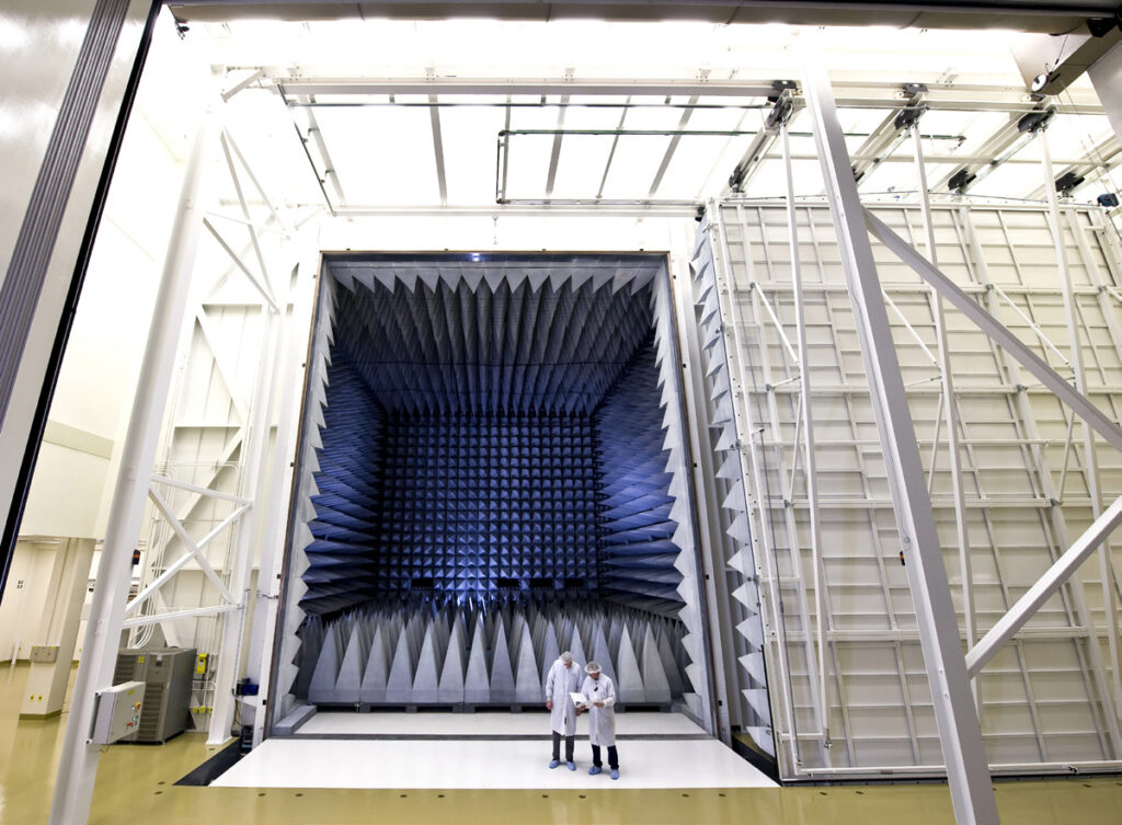
ETS‑Lindgren installed a large RF shielded anechoic chamber for Passive Intermodulation (PIM) emissions testing of satellites at the Lockheed Martin Company (LMCO) production facility in Sunnyvale, California. Certifying that a LMCO satellite is not producing PIM emissions expedites development schedules, allowing LMCO to better meet commitments to its customers.
Lockheed Martin awarded ETS‑Lindgren the chamber due to its unique capability in offering a high level turnkey solution as well as for its expertise gained over several decades of providing large, complex RF shielded chambers for U.S. government projects. With a critical project due date, Lockheed Martin also appreciated ETS‑Lindgren’s proven record of completing projects on schedule.
The culmination of this successful collaboration resulted in a three-year contract. The decision to choose ETS‑Lindgren was influenced by the long-standing relationship in all Beaumont locations, the track record of maintaining a clean and efficient operation, flexibility compared to competitors, and demonstrated experience in working with various door suppliers.
The chamber was designed to test commercial satellites as part of the Mobile User Objective System (MUOS) – a next-generation narrowband tactical satellite communications system created to significantly improve ground communications for U.S. defense forces on the move.
Lockheed Martin addressed the MUOS project in two phases. Phase one involved the large RF shielded sliding door that was to be installed on the new chamber. Phase two involved the design and installation of a large RF shielded chamber. Placing the contract award for both the door and the chamber with ETS‑Lindgren demonstrates Lockheed Martin’s confidence in the company’s turnkey solution.
Immediately following contract award, ETS‑Lindgren worked with the LMCO architectural firm responsible for the parent building that would house the PIM chamber.
Details such as slab thickness, floor height, grade beam locations, perimeter line loads, and column loads are an example of some of the requirements ETS‑Lindgren specified in advance of project implementation. This collaboration resulted in a cost-effective approach that ensured the parent building was well-suited and ready to house the specialty anechoic chamber.
PIM Chambers Technical Specifications
- Anechoic test chamber dimensions are 58 ft (17.6 m) L x 1 ft (15.5 m) W x 43ft (13.1 m) H (approximate shield to shield)
- Designed for testing satellites to determine ultra high frequency (UHF) PIM emissions ≤ 140 dBmW at 294 MHz and 317.5 MHz
- Lowest operating frequency range is 240 MHz
- Highest operating frequency range is 20 GHz
- The chamber was constructed of modular, fully welded shielded panels to expedite installation
- Compliant with the Clean Room Class 100,000 requirement per document 2280728
- Site floor loading and chamber support a test device with dimensions of 24 ft (7.3 m) L x 28 ft (8.5 m) W x 16 ft (4.8 m) H and weight of 35,000 pounds
- Meets all state and local earthquake building codes
- Specialty high hat light fixtures provided were exclusively designed for the PIM shielding requirement
RF Shielding Performance
Shielding effectiveness was tested and confirmed as 120 dB from 200 MHz to 40 GHz
RF Shielded Doors
- Model SRFSD/F/A-100 RF shielded sliding equipment door, 30 ft (9.1 m) W x 35 ft (10.6 m) H, a door ramp (lift) system with 17.5 ton loading capability.
- Model RFSD-F/A 100 RF shielded emergency/personnel door, 5 ft (1.5 m) W x 8 ft (2.4 m) H
- All doors feature a flush threshold as well as push button automatic opening and closing to facilitate moving the Device Under Test (DUT) into the chamber
Anechoic Absorber Treament
- Performance frequency range is 240 MHz to 20 GHz with an absorber reflectivity of 35 dB or better from 240 MHz to 20 GHz
- Full coverage is provided throughout the chamber using EHP-72PCL absorber
- RF power handling of 200 V/m capability (0.1 Watt/in² power density) continuous wave
- Capable of accommodating 0.5 W/in² throughout chamber
- Fire retardancy is provided in accordance with industry standards, including NRL Report 8093 (Tests 1, 2 and 3), UL 94 HBF, and others
- Removable floor absorber provided
- The absorber was painted white to brighten the chamber
Special Temperature and Humidity Control Requirements
- Temperature range is controlled for 65 to 80 degrees F operation
- Relative humidity is maintained at 30-60%
- Waveguide air vents are designed to pass 2000 cubic feet of air per minute – without a significant pressure drop – to facilitate DUT cooling.
About ETS‑Lindgren
ETS‑Lindgren is an international manufacturer of components and systems that measure, shield, and control electromagnetic and acoustic energy. The company’s products are used for electromagnetic compatibility (EMC), microwave and wireless testing, electromagnetic field (EMF) measurement, radio frequency (RF) personal safety monitoring, magnetic resonance imaging (MRI), and control of acoustic environments.
Headquartered in Cedar Park, Texas, ETS‑Lindgren has manufacturing facilities in North America, Europe, and Asia. Additional information about ETS‑Lindgren is available at www.ets-lindgren.com. Additional information about ETS‑Lindgren’s parent company ESCO and its subsidiaries is available at www.escotechnologies.com.