Northeastern University Innovation Campus
At the grand opening held on the Northeastern University Innovation Campus, attendees toured the new Expeditionary Cyber and Unmanned Aerial System (UAS) Flight Facility, the result of the Kostas Institute Partnership in Counter UAS Technology. Representatives from the US Air Force Research Lab and Hanscom Air Force Base as well as the US Naval Research Lab discussed the significance of the unique UAS Flight Facility at the grand opening. To ensure the facility would produce cutting edge research and development, management at Northeastern University contacted the experts at ETS‑Lindgren. Northeastern University valued ETS‑Lindgren’s documented experience in chamber design and construction, program management, and logistics management. ETS‑Lindgren initially worked with Northeastern University under an engineering and design contract to determine all necessary test requirements. Once that effort was finalized, ETS‑Lindgren manufactured, installed and integrated a fully-functional UAS Flight Facility on time and within budget.
Project Overview
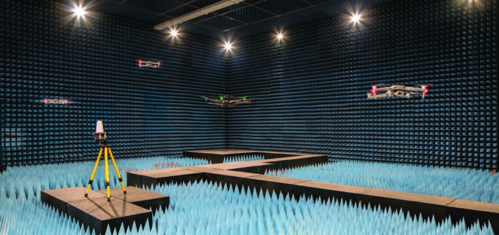
A large RF shielded anechoic chamber is part of an indoor drone (in-flight) test facility at the Kostas Research Institute UAS Lab in Burlington. The chamber is fully lined with microwave absorber material and features two large access doors that allow Northeastern University to fly drones between the shielded chamber and a protected outdoor flight test area. A large support frame located on the chamber ceiling supports the mounting of antennas. ETS‑Lindgren designed the chamber to meet Northeastern University’s goal for a multi-purpose structure with maximum configurability and flexibility.
RF Shielded Chamber
- RF shielded enclosure with nominal inside shield dimensions of 15 m x 14 m x 6 m (59 ft x 48 ft x 21 ft). Constructed of Series 81 shielded modular panel sections that are assembled with a clamping system into a self-supported enclosure.
- Modular RF shielded pit 1.5 m x 1.5 m x .4 m (60 in x 60 in x 18 in high) for Multi Access Positioner System (MAPS) recess including shielded cover.
RF Shielded Doors
- Fully-automatic electro pneumatic sliding RF shielded equipment door, 3 m x 3 m (10 ft x 10 ft), installed on the north chamber wall. The door is specially designed to provide a high level of RF isolation, easy automatic operation, and flush chamber access while also supporting the weight of hybrid absorber materials.
- Dual-leaf RF shielded equipment door 3 m x 3 m (10 ft x 10 ft) installed on the east chamber wall.
- Single-leaf 1.2 m x 2.1 m (4 ft x 7 ft) manual RF shielded personnel door installed on the south chamber wall.
Absorber
- The chamber features full coverage on the walls, floor and ceiling of Model EHP-18PCL 46 cm (18 in) polyurethane microwave absorber. Floor absorber is removable.
- FlexSorb™ coated EHP-18PCL was provided for all pyramidal floor absorber. It was also provided for all chamber door surfaces and around each door’s immediate perimeter in a .6 m (2 ft) band. FlexSorb™ coating creates durable absorber tips that resist breakage, which is especially important for these high traffic areas.
Positioning Equipment and Software
- For far-field antenna pattern measurement testing, ETS‑Lindgren provided Model 2115CR MAPS designed to minimize EMI noise and offer minimal physical obstruction of RF fields. It offers structural integrity with low mass and low RF reflective dielectric materials. The base unit has two different attachments: light-duty and medium-duty. The medium-duty attachment can handle up to 11.3 kg (25 lbs).
- The EMQuest™ EMQ-100 Antenna Measurement Software provided offers a wide range of fully parameterized test methods for measuring basic antenna performance metrics as well as testing both radiated and conducted performance of various wireless devices. The baseline test suite includes fully automated 2-D (polar) and 3-D (spherical) pattern measurement capabilities as well as various frequency response measurements for both passive antennas and active wireless devices in either transmit or receive mode.
NEMP Test System
- For high-power drone susceptibility testing, ETS‑Lindgren partnered with HV Technologies and Montena to provide a pulse generator according to MIL-STD-461 versions E, F and G/RS105.
- Maximum effective voltage is +5 kV to +80 kV, positive polarity.
- The radiation line offers a test amplitude of up to 50 kV/m. Overall dimensions are 6.6 m long x 2.5 m wide x 1.8 m high (21 ft x 8 ft x 6 ft); line length is 3.6 m (12 ft).
Antenna and Camera Support
- A fiberglass antenna support frame 11 m x 11 m / 1.5 m (35 ft x 35 ft / 5 ft on-center grid) was mounted to the underside of the ceiling panels using a threaded rod nested in absorber.
- Strut mounting standoffs for each camera were mounted six (6) per wall around the entire chamber to support twenty-four (24) OptiTrack® Prime 17W Gigabit Ethernet HD cameras provided by Northeastern University.
Accessories
- ETS‑Lindgren provided LED lighting, waveguide air vents, viewing windows, RF power and signal line filters, connector panels and penetrations to meet the various test needs of Northeastern University.
Chamber Performance
A shield verification test was performed in general accordance with the test methods of MILSTD-285 and IEEE 299 at four (4) frequencies up to 10 GHz as follows:
- Magnetic Field:
20 dB @ 1 kHz
56 dB @ 10 kHz
100 dB @ 150 kHz - Electric Field:
100 dB from 150 kHz – 50 MHz - Plane Wave:
100 dB from 150 kHz – 50 MHz - Microwave:
100 dB from 50 MHz – 1 GHz
About ETS‑Lindgren
ETS‑Lindgren is an international manufacturer of components and systems that measure, shield, and control electromagnetic and acoustic energy. The company’s products are used for electromagnetic compatibility (EMC), microwave and wireless testing, electromagnetic field (EMF) measurement, radio frequency (RF) personal safety monitoring, magnetic resonance imaging (MRI), and control of acoustic environments.
Headquartered in Cedar Park, Texas, ETS‑Lindgren has manufacturing facilities in North America, Europe, and Asia. Additional information about ETS‑Lindgren is available at www.ets-lindgren.com. Additional information about ETS‑Lindgren’s parent company ESCO and its subsidiaries is available at www.escotechnologies.com.