EMI/RFI Shielded Waveguide Air Vents
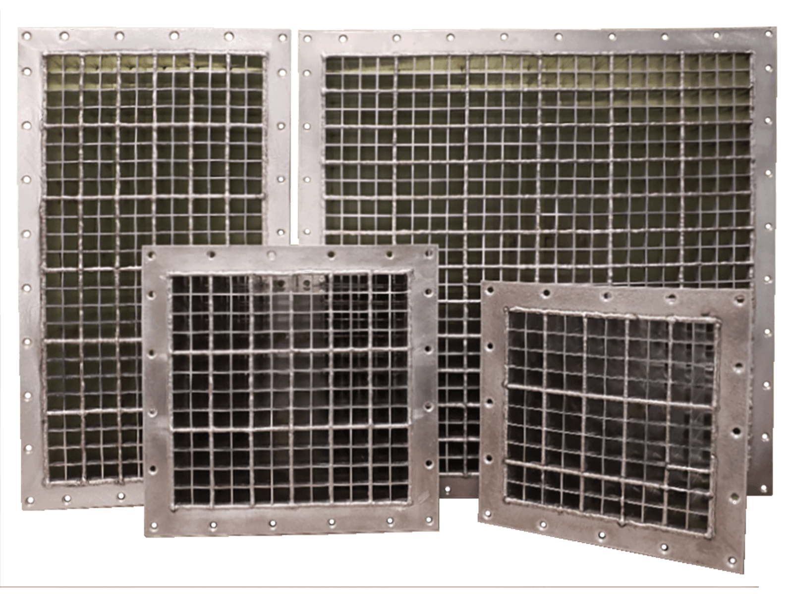
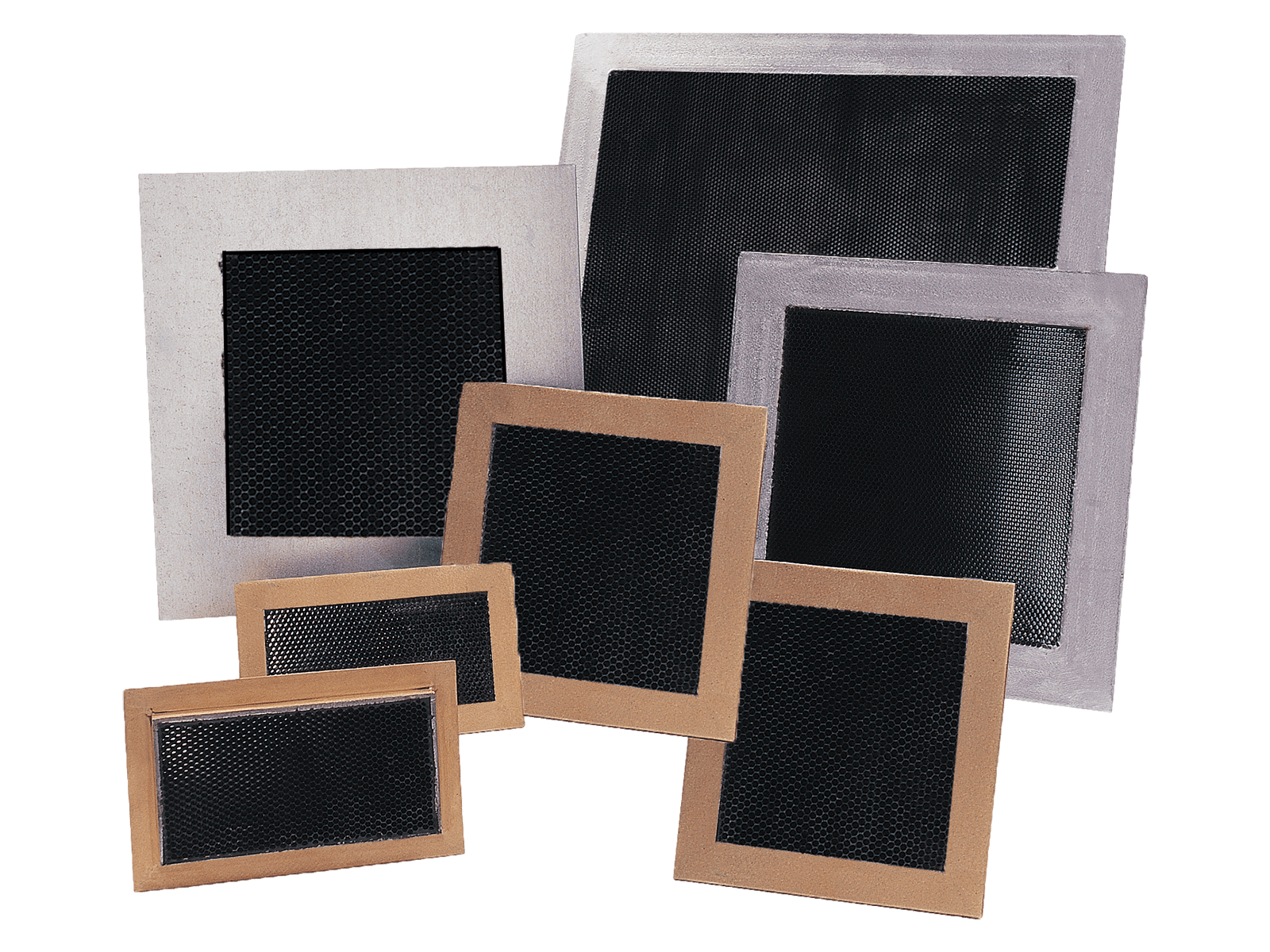
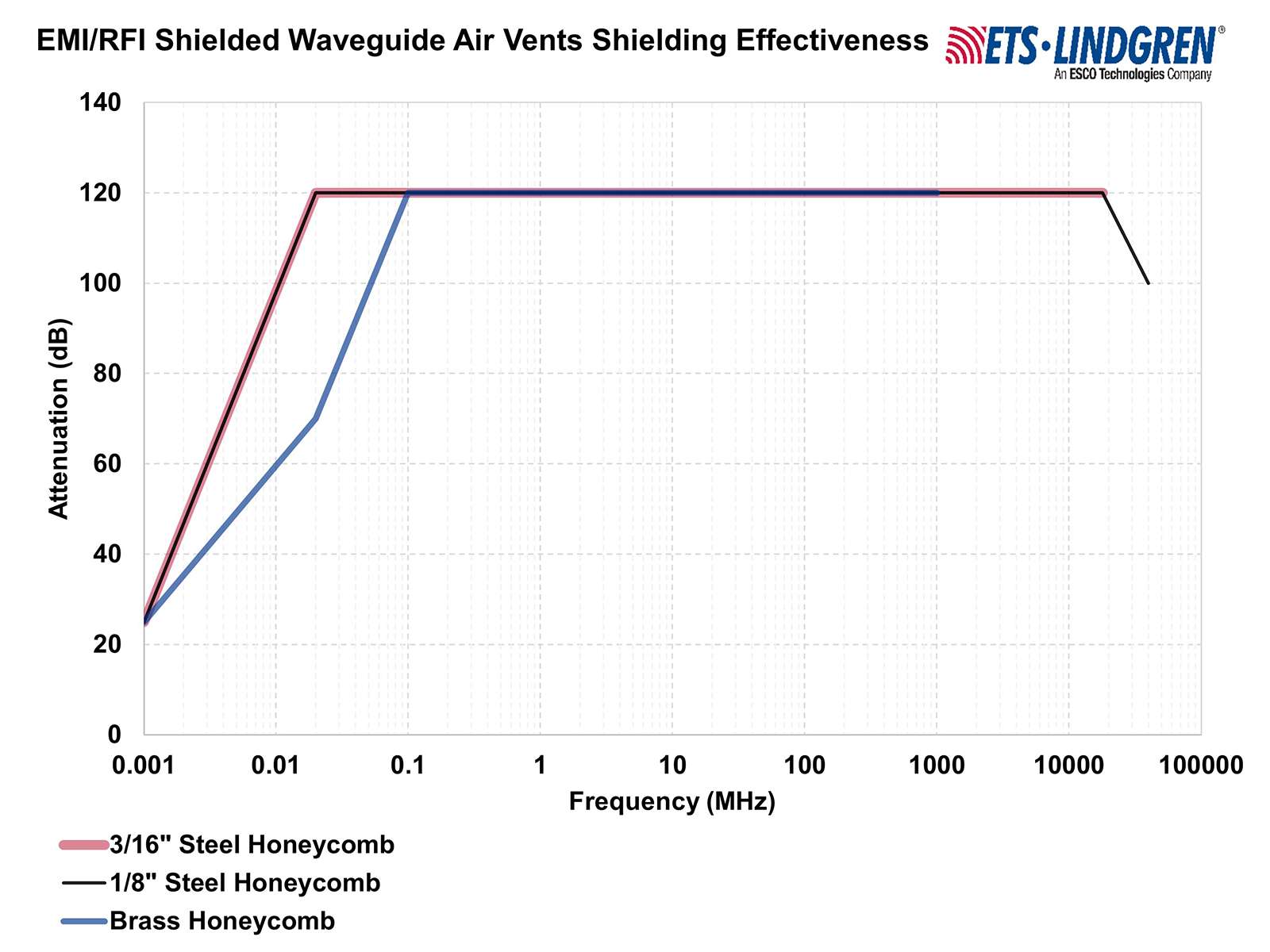
EMI/RFI Waveguide Air Vents provide efficient airflow while maintaining high RF attenuation using precision-built honeycomb structures in brass or steel.
Add to FavoritesRemove from Favorites
Add to Favorites
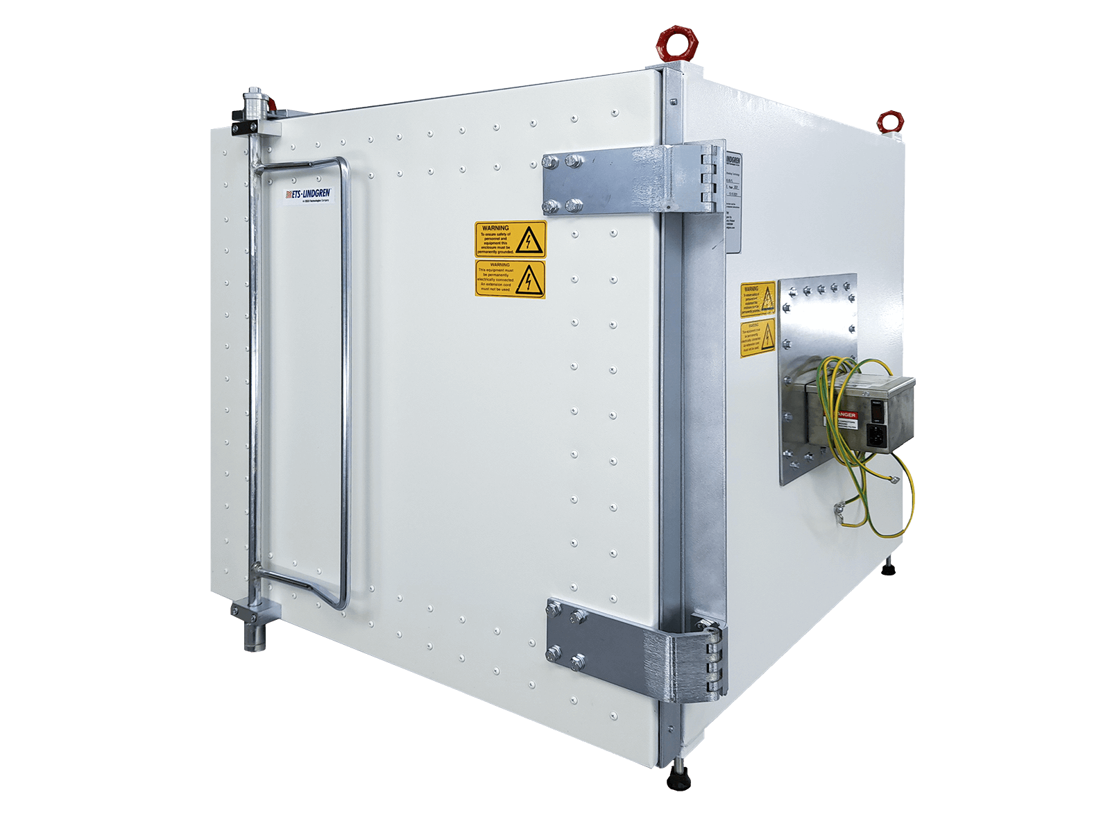
EMI/RFI Waveguide Vents for Shielded Airflow
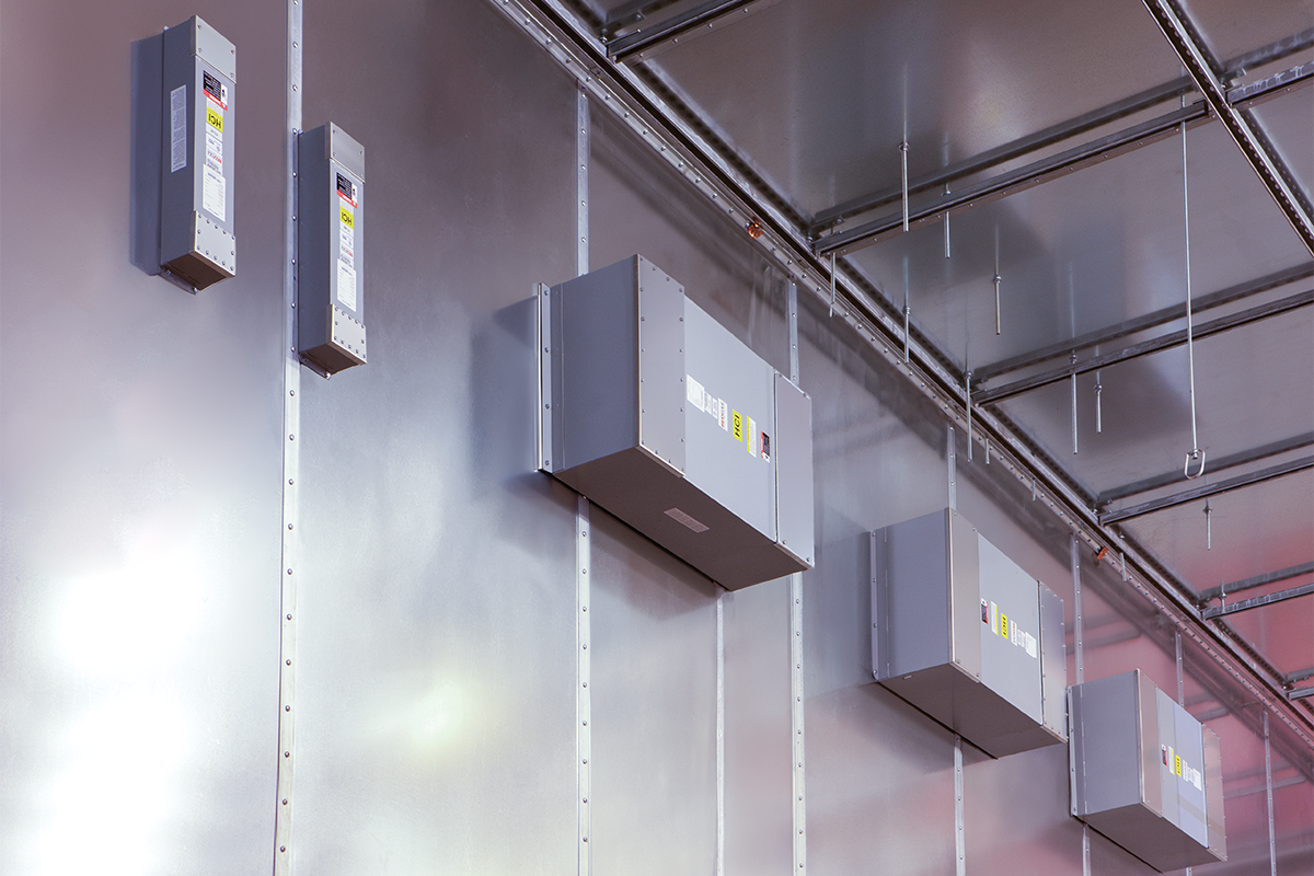
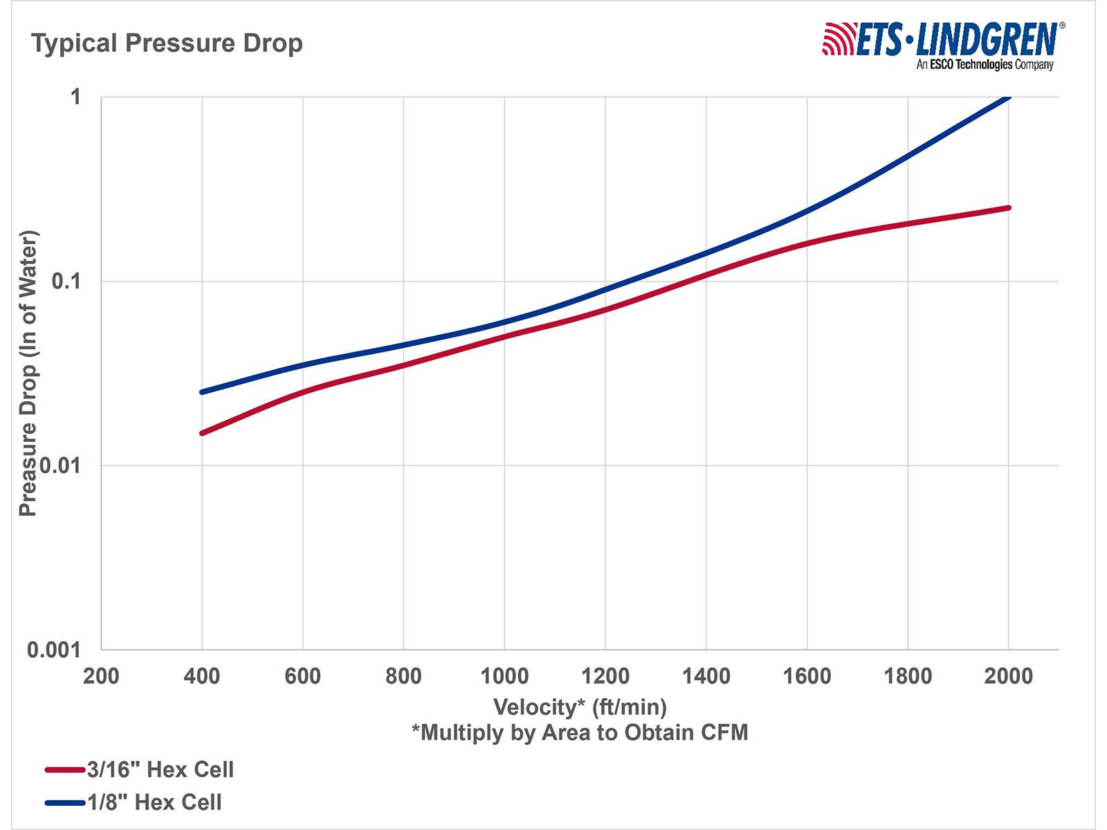
EMI/RFI Waveguide Air Vents are engineered to deliver high shielding effectiveness with minimal airflow restriction, making them ideal for RF-sensitive rooms and controlled environments. Available in steel or brass honeycomb cores, the vents are precisely solder-fused for consistent performance and long-term durability. Their honeycomb geometry balances pressure drop with strong attenuation across low-frequency magnetic fields and high-frequency microwave ranges. Multiple mounting options—including soldering, welding, and gasketed interfaces—allow seamless integration with a wide variety of enclosure designs. This flexible configuration ensures dependable sealing, corrosion resistance, and stable airflow characteristics tailored to each installation.


Case Study : Category : Utilities
Can your business afford to be vulnerable to an electromagnetic pulse (EMP) attack? What if your business never recovers from the attack? These were questions that the executives and Board of Directors…

Case Study : Category : Automotive
With the goal of installing an internationally renowned drive motor EMC test facility, NAST partnered with ETS‑Lindgren to design and install an EMC anechoic chamber with a dynamometer for real-world automotive testing…

With demand growing for automotive EMC testing of full vehicles and components as well as for commercial, consumer, medical, and wireless products, TÜV SÜD Italy investigated options for expanding their test capabilities.…