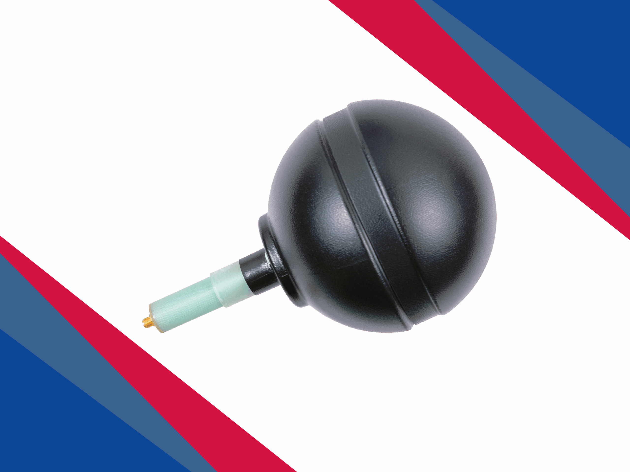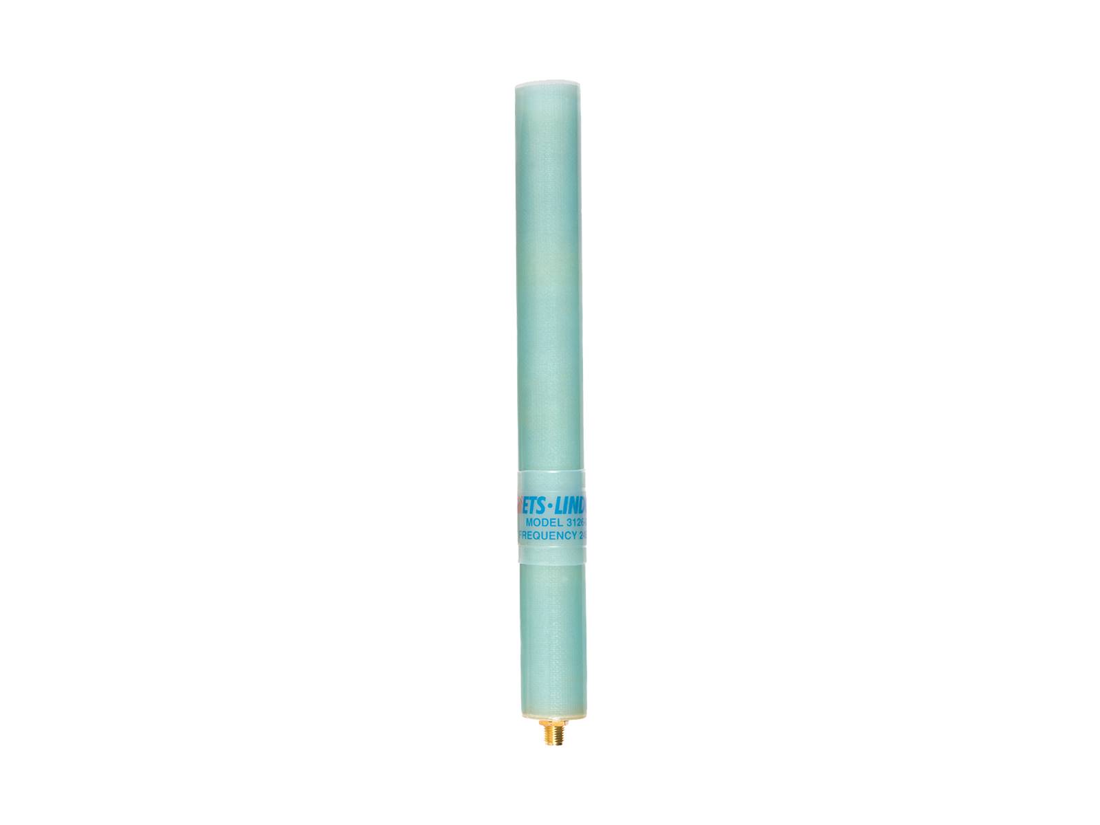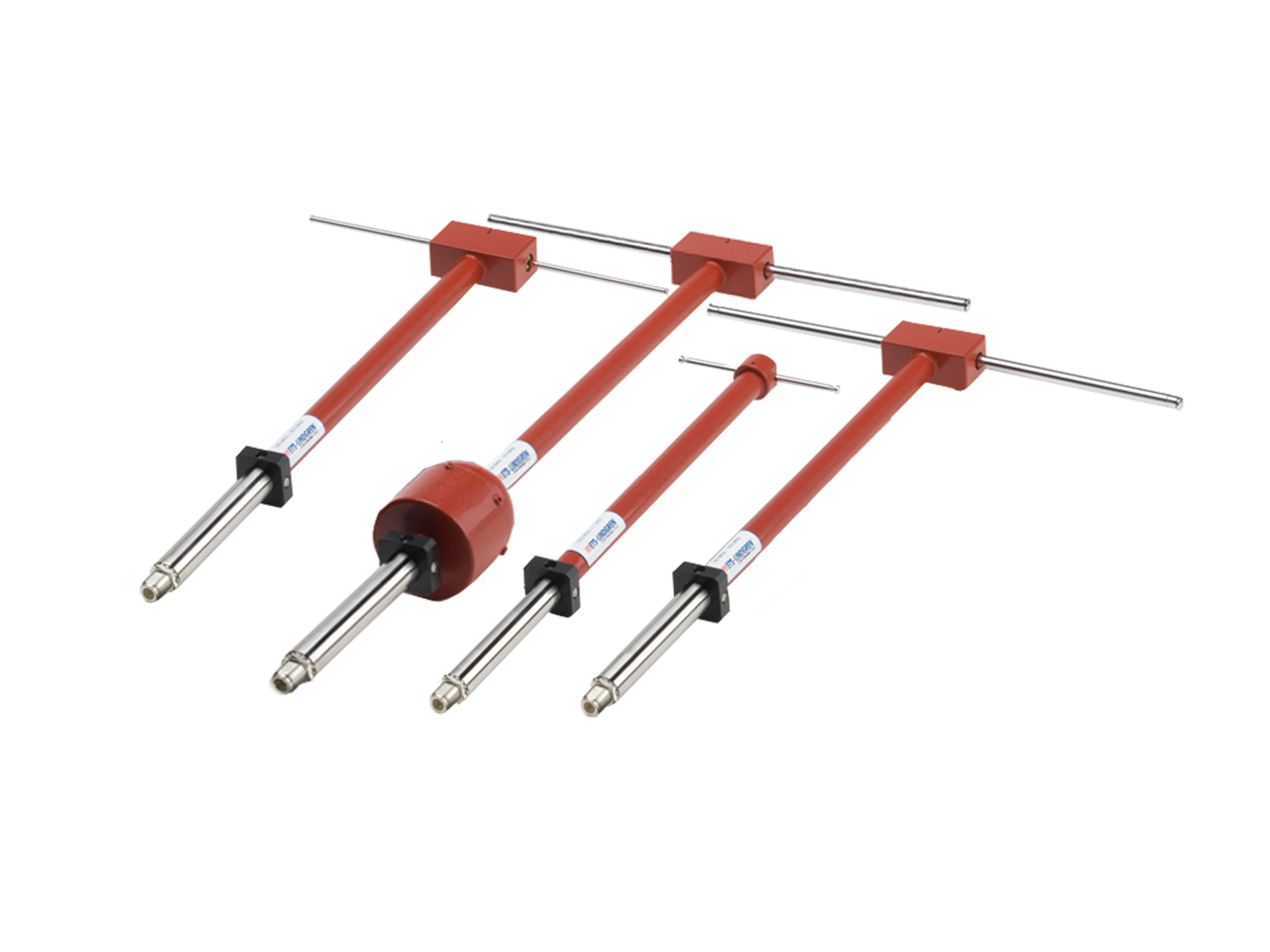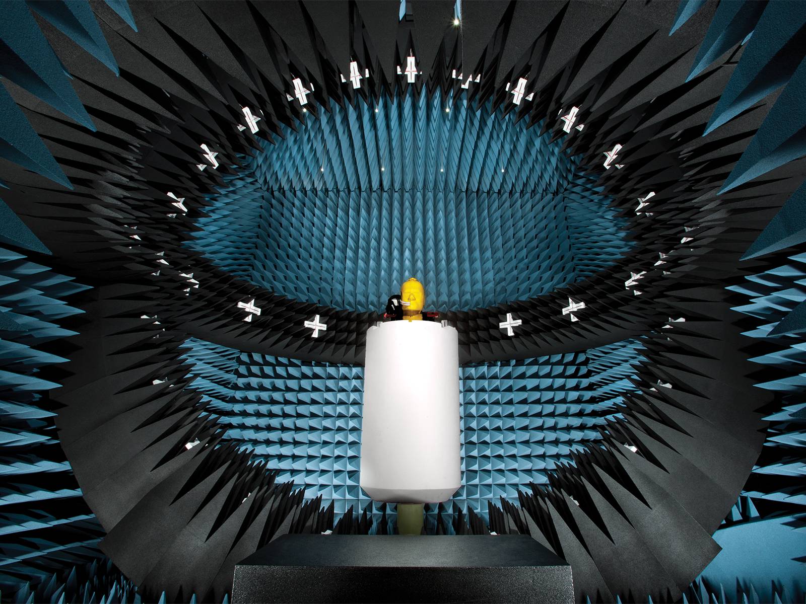
Omnidirectional Dipole Resonant Loop Antenna for Wireless Band Testing
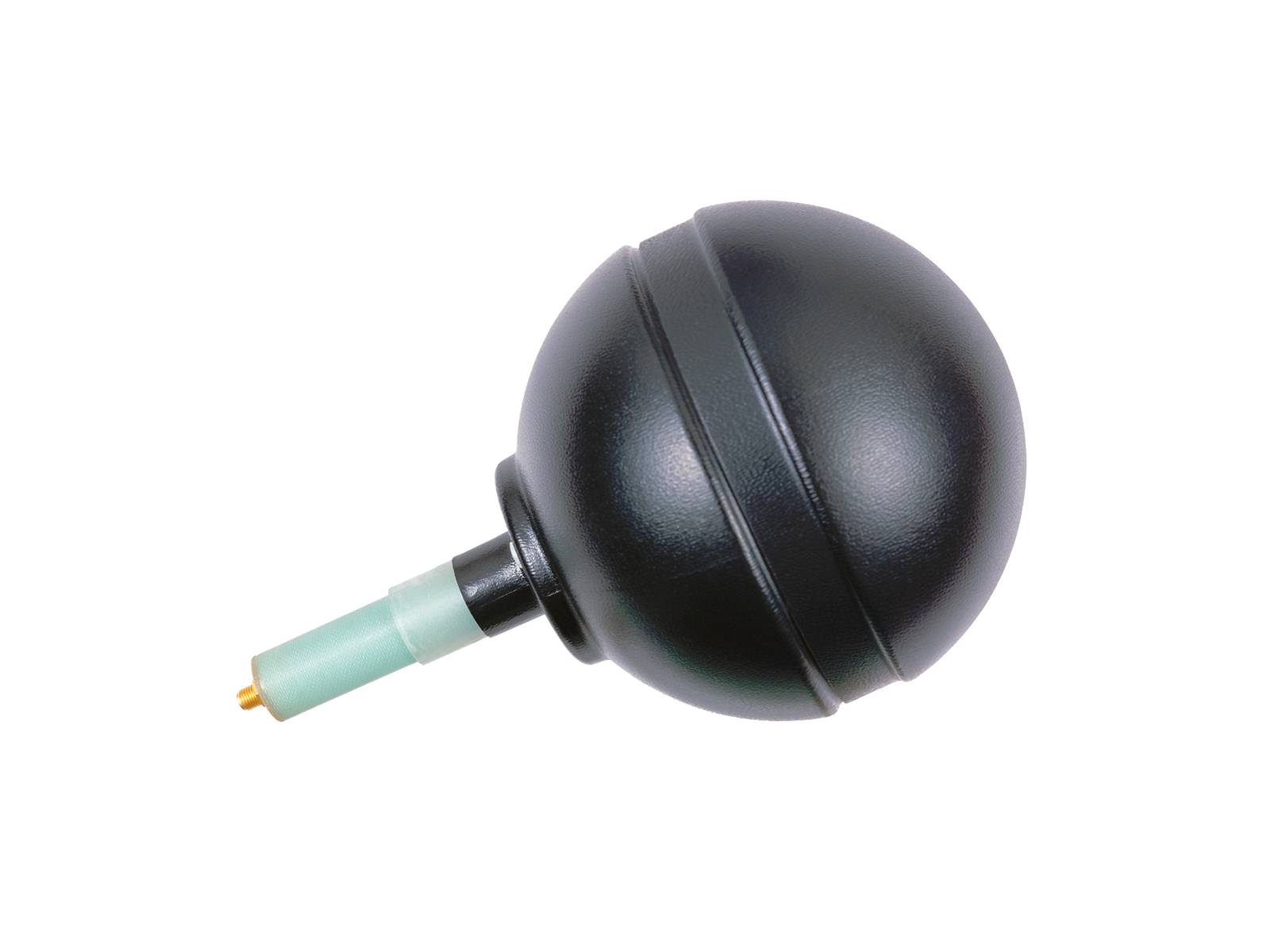
The Model 3127 Resonant Loops are omnidirectional dipole antennas designed to meet the Cellular Telecommunication and Internet Association's (CTIA) ± 0.1 dB symmetry requirement for ripple test measurements at the labeled center frequency. They have a magnetic dipole pattern approaching that of a half-wave resonant electric dipole. The pattern produced has the same peak and null orientation as that of a sleeve dipole oriented along the same axis, but with the directions of the electric and magnetic fields reversed. The loop design allows the antenna to be end-fed to avoid cable and feed-point interactions that interfere with the symmetry of the antenna.
Key Advantages:
- Range of Frequencies to Cover Wireless Device Bands
- Designed for CTIA Ripple Test
- Meets CTIA ± 0.1 dB Symmetry Requirement